|
|
|
Wear Testing
|
|
|
|
Test methodology
|
|
|
|
A metal with good wear characteristics exhibits good edge retention and resistance
to surface scratching during paring or planing operations. A dull edge from paring
would consist of a large loss in edge retention and show scratches in the lapped
non-bevel surface, as well as the micro-bevelled face. It its less desirable to
have scratches in the non-bevel surface because from a re-sharpening perspective
it is easier to remove scratches on the much smaller micro-bevel surface.
|
|
|
|
During paring and planing, the blade does see an initial impact when it comes in
contact with the wood, but this is much smaller than the forces seen in impact testing.
The constant forces applied during paring and planing are longer in duration.
|
|
|
|
|
|
Our wear testing apparatus consisted of a small DC motor that drove a plane blade
assembly jig in an oscillating linear motion that simulated paring or planing. The
paring jig assembly was designed to hold test blades bevel down at a controllable
relief angle.
The blade's relief angle was consistently set at 2°. This was determined by experiment
to be the lowest relief angle that worked for our controlled shaving thicknesses
of 0.020" to 0.030". (Previous testing proved that material could not be pared for
thin shavings with a 0° relief angle.)
The material we cut was MDF, chosen for its uniform consistency and abrasive quality.
(Note: we don't recommend you plane MDF with your Veritas® planes, even with
a PM-V11 blade. Please don't. Trust us.)
|
|
|
|
|
The MDF was cut to 6" widths and clamped above the blade and held perpendicular
to the direction of the blade movement. After the blade cut through the entire MDF
board, the board was lifted on the return stroke to prevent wear scratches on the
blade as the blade was being brought back to the starting point of the cycle. No
pressure was applied to lower the board back onto the fixture; gravity alone was
enough to hold the MDF down for the blade to pare through it.
|
|
|
|
The wear testing was performed at three micro-bevel angles: 20°, 25° and 30°. All
blades pared a set distance and were catalogued at linear distances of 10', 20'
and 40'. The blades that continued to perform well were then run for an additional
60', totaling a distance of 100'. O1 and A2 blades also pared for 100' for baseline
comparison.
|
|
|
|
Test results
|
|
|
|
The blades were scored based on the amount of edge failure after a set measure of
linear footage pared. For graphical purposes, the top-scoring material was assigned
a score of 10 and the lowest-scoring material was assigned a score of 1. Intermediate
performing materials were assigned scores on a relative linear basis. (Note that
this does not mean that the top metal scored 10 times better than the lowest metal.)
|
|
|
|
While all blade configurations were assigned code letters for testing, we have revealed
the scores of the O1, A2, M4 and PM-V11 alloys.
|
|
|
|
Material
|
Wear Test Score
|
|
Z-1
|
10
|
|
PM-V11
|
9
|
|
M4
|
9
|
|
Y-1
|
9
|
|
S
|
8.5
|
|
W
|
8.5
|
|
X
|
7.5
|
|
P
|
7.5
|
|
R-1
|
7
|
|
N1
|
6.5
|
|
N-2
|
5.5
|
|
R-2
|
5
|
|
V-1
|
5
|
|
V-2
|
5
|
|
Q
|
4
|
|
Z-2
|
4
|
|
T-1
|
3.5
|
|
T-2
|
3
|
|
Y-2
|
3
|
|
A2
|
1.5
|
|
O1
|
1
|
|
|
|
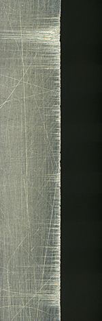
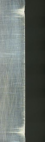
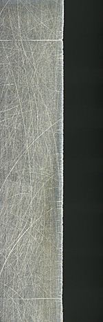
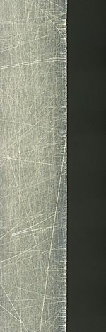
Sample Wear Test Images
|
|
|
|
|
|
|
|
|
|
|
O1
|
|
A2
|
|
M4
|
|
PM-V11
|
|
|
|
Note: the bands of horizontal scratches on the blades shown above
are from the edges of the MDF we used in the Wear Test. The edges are harder than
the interior of the MDF and thus they wear the blades more in those areas. You can
see that O1 and A2 blades had significant wear on the edges of the MDF, whereas
the M4 and PM-V11 blades had very minor wear.
|
|
|
|
|